Saturday, December 13, 2008

FIRST Lego League

I'm sitting here at the SHARC table for the FIRST Lego League Championship here in Denver, CO.

Really cool to see all the interest and enthusiasm in robotics amongst the kids! We've had a lot of visitors here.

The Wall-E robot is by far the most popular of course.

But the firefighting robots, ol' Pokey and Physignathus, are getting a fair share of attention, too.

Wednesday, December 3, 2008

Logic Analyzer

I went to my first SHARC meeting in months. Was good to meet some new folks and say hi to the regulars.

FIRST has started up so am thinking about attending their next meeting on Sunday. I've wanted to get involved in this kind of thing so now is a good opportunity.

Aside from a good time, one of the guys gave me a Hewlett Packard (HP) 1650A logic analyzer (see photo). Could be interesting and even useful, who knows. The machine didn't come with probes (they are called "pods") or the operating system disk. I wondered if I could get this thing working.

If you've never resurrected obsolete equipment you should at least try it once. It's a hoot. Technoarcheology. (Remind me to tell you about the computer club we formed in college...)

The pods are available on that famous auction site for generally $30-50 each and the 1650A can take 5 of them. Hm.

I can make the boot disk for free with a little digging (for information) and a spare 720K 3.5" floppy. The machine requires this boot disk to be formatted using LIF (Logical Interchange Format) -- just to make this exercise a little more challenging. Here are the steps to building a boot / disk / operations system disk:


Choose 'DOS to LIF Copy'
Use these settings:
- DOS File Name: (File you want to copy, start with SYSTEM_)
- File format conversion: Binary image: No format change, user-def. type
- All other can stay the same
With the cursor on the File format conversion line, press F6 to set
the file type.
For system files (SYSTEM_ and PVTEST_)
- User-defined LIF file type : C001
- Implementation specific field: 534F544F
For config files
- User-defined LIF file type : C120
- Implementation specific field: 534F544F
For other files (Reverse Assemblers, etc)
- Unknown.
- If you have a disk list it with LIFUTIL. LIFUTIL shows the
type as a signed decimal number. Convert it to hex.


Hope this helps someone out especially in finding all the necessary software. Took me an hour to find a download site for the operating system... I was searching all over when all I had to do was search for 1650A on the Agilent site. Duh! :)

As you can see from the photo above I have the machine booted successfully and was able to load a couple of the demos. You can probably tell that the display is really dim. The setup manual explains that there's an intensity knob on the back. No dice. The service manual explains there is a "sub bright" control inside that can be used to adjust the base intensity setting. I'll try that next. Failing that, some type of electronic repair may be required.

Sunday, October 19, 2008

Hectic!

It's been a hectic and kind of rough couple weeks with work travel, workload, school, and family/personal stuff going on... But I've managed to squeeze in a few things.

First, someone was kind enough to make two broken inkjet printers available on Denver Freecycle. Turns out there are three motors in each, of varying sizes. Lots of gears, too. And a rotary encoder. And some rubber rollers that maybe can be turned into wheels. I am hoping that I can use this stuff in robots including Squeaky the Record Cleaning Robot.

On that topic, Squeaky hasn't progressed much. I've experimented with using the vacuum to lift off cleaning fluid and gunk from the record but the suction is high enough that it wants to grab onto the record so I am pondering some options on how to retain the suction without lifting the record off the platter.

I also took apart a 3-in-one stereo system and salvaged a transformer and several small motors (two for the tape deck and two for the 3-disc CD changer). Maybe something to use for a tiny robot or two. The vacuum fluorescent display appears damaged but there's another in a DVD player that I'd like to play with as the status display for Squeaky.

Tuesday, September 16, 2008

Squeaky: Chassis Done

Squeaky < prev | next >

Time is running out for robotics. My last class of the year started last night and the spectre of impending homework, reading, projects... Meanwhile my shelves are now packed with hundreds of recently acquired, filthy records pining away for a good record cleaning machi--err, record cleaning robot. Squeaky. As you know I'm kind of winging it on this one.

Squeaky is going to use a motor/sprocket/tooth-belt assembly from a bread machine with an idler wheel attached, so the entire assembly needs to pivot. Idler wheel pressure will be controlled by a spring. The previous incarnation led to a rather floppy assembly due to play in the single bronze bushing.

The new version uses a 3/8" threaded rod as the axle, with two bronze bushings to control wobble. I started with a 3/4" plywood base (leftmost picture below) of 13"x15" based on some mockup measurements. The base houses the lower bushing. A hole with chamfer (middle picture) makes it easier to hammer the bushing into place. A wood tower houses the topmost bushing and the threaded rod goes through both (rightmost picture below).


Lock nuts will cinch against the thrust surfaces of the bushings and hold the threaded rod and bushings in place and allow for end play adjustment.

With the pivoting rod in place, all that's needed is the serrated lock nuts to clamp on either side of the motor platform and now the pivoting drive assembly is held securely with nearly no wobble.

In the picture (above right) despite the dreadful fuzziness, you can make out the lock nut on the bottom and the serrated lock nut above it, holding up the bottom of the motor assembly. Another neat feature of this arrangement is that the height of the motor can be adjusted precisely.

The upper platform is 3/4" plywood, same dimensions, into which I installed the turntable spindle assembly, and cut a hole through which the idler wheel will protrude. It's not pretty but it works and it won't be visible during normal operation.

The top platform is supported by four 1" square dowels screwed into place form top and bottom (below left). Also not pretty. But, I do plan to dress this thing up once I get the details worked out. I had to make a few minor modifications but in the end, it seems to work, there's room for the vacuum, for the fluid reservoir, etc. The mechanism seems a lot tighter and more precise than my earlier mock up.


Regarding the electronics... I accidentally blew up the transformer that came with the bread maker but I was able to salvage an entire power supply including fuse, switch, transformer out of the junk linear tracking turntable I got for free and it all works beautifully with my homebrew bridge rectifier (above right).


Squeaky < prev | next >

Saturday, September 13, 2008

Esquire E-Ink Magazine Cover

I'm sure you've heard about the Esquire E-Ink cover? Everyone's blogging about it so I guess I have to, too. Picked one up today.The thing doesn 't do enough to impress my wife :) but I think it is pretty neat. Better, it appears to be hackable according to Make. It's got a PIC processor, 5-pin programming header, and two e-ink flexible screens that apparently can be switched. I notice the development kits over at e-ink cost $1500-3000 so... no plans to create my own custom robot displays until I win the lottery... I wonder if you can do anything with just the processor...

Saturday, September 6, 2008

Squeaky: Power Supply and Motor Demo

Squeaky: < prev | next >

Squeaky's 24V motor power supply is operational. Eureka!

I blew up the bridge rectifier that came with the bread maker so I used four 1N1004 rectifier diodes that were in the parts bin to make a diode bridge with a 1000µF cap in the middle to smooth out ripple and provide a little reserve current. My very first AC-DC power supply!

I reused the bread maker transformer which is a 24VAC with center tap. I noticed Radio Shack had a number of these for sale. I am hoping to figure out a way to do a dual output supply but for now I have the ~32VDC that I need.

The only downside is that the motor spins a bit slow, so with the additional reduction of the small rubber drive puck, the platter is spinning quite slow. That may need correcting.

Squeaky: < prev | next >

Thursday, September 4, 2008

Squeaky: Why Vinyl?

Squeaky: < prev | next >

You may be wondering why a guy that's into robotics would want anything to do with records. They're so last millenium! I've always enjoyed the experience of playing records and I recently discovered that LPs can rival CD sound quality. Provided the records are well cleaned and played on a good turntable.

As we all know, the word robot comes from the Czech robota, figuratively meaning drudgery, or hard work. Nothing could better describe the process of cleaning LPs. It really sucks. And that's where Squeaky comes in.

In case you still don't believe LPs can sound good, here's an audio clip comparing the CD and LP versions of the same recording of Mozart's Oboe Concerto. Have a listen.

Squeaky: < prev | next >

Squeaky: Drive Mockup

Squeaky: < prev | next >

Squeaky the Record Cleaning Machine is coming along nicely. Last night I spent a few minutes mocking up the drive mechanism (left) after a short trip to the hardware store.

If you look closely, there is a nut between the white plastic driven sprocket and the motor sprocket, slightly off-center. That is the pivot point for the drive chassis. With a spring forcing the idler wheel against the platter as shown, precision mounting isn't necessary, the amount of force can be made adjustable, and the device is wear tolerant.

The pivot itself is super simple as the series of pictures below demonstrate. A bronze bushing is press fit into a block of wood (below left) and a 3/8"x2" bolt slides through the bronze bushing acting as the axle.

The non-threaded portion of the bolt rides in the bushing. The two serrated lock nuts (below center) clamp onto the drive chassis which required one of the existing holes to be enlarged. Note the washer pictured below. It's probably unnecessary and will just wear out; it would be better for the nut to ride against the bushing directly.


The block was a bit thicker than the bushing so for the mock up, a hole in the block on the bottom side (above right) allows the bolt to slide up against the bottom of the bushing and also allows the entire assembly to be mounted to a flat surface without interference.

I realize none of this is very pretty. It is a mock up after all. Now that I have a sense of how it goes together, I'll revise the mounting blocks for the platter and drive chassis, making them one block, and more compact. If you can't tell I am pretty much making this up as I go, rather than trying to draw / draft it all out ahead of time.

Meanwhile I'm in the process of procuring some inkjet printers that will donate their stepper motors for controlling the motion of the cleaning, scrubbing, vacuuming arm(s). My only concern with using stepper motors is the expense of a controller. Other alternative: a cheap servo, if it is strong enough to do the work.

Squeaky: < prev | next >

Thursday, August 28, 2008

Squeaky: Platter Drive

Squeaky: < prev | next >

One of the key features of a record cleaning machine is the ability to spin the record without manual intervention. I'm getting really sick of cleaning records by manually spinning them on my turntable while I scrub.

Some folks on AudioKarma.org had suggested use of a bread machine, presumably because it uses a fairly high torque motor and some kind of gear reduction.

Upon dissecting the $2 bread maker I got from Goodwill, I found a metal plate onto which a motor and drive mechanism are mounted. As shown in the pic to the right, the motor drives the stirring mechanism on the opposite side of the plate via a tooth belt.

The white cog wheel is attached to a stainless steel drive shaft riding in a bronze bearing by way of a 6mm nut. The drive mechanism is attached to the drive shaft and engages the stirring gizmo in the bread bucket to stir and knead the bread, similar to how the blades of a blender are coupled to the blender motor.

But how to drive a turntable platter? The two I had on hand spin on greased bearings attached to a mounting plate to affix them to a horizontal surface (see pic to the left).

They are both from belt drive turntables. Should I try to use a turntable belt? These are usually low tension belts and will slip with the slightest drag on the platter. I needed a higher torque, higher traction solution.

I want to keep this simple, cheap, and practical with minimum fabrication involved; I don't have a machine shop and I don't want to spend a fortune on this project. Those constraints eliminate a lot of design options. Direct drive would've required fabrication of some type and possibly re-engineering the drivetrain making this an unnecessarily hard problem to solve.

Why not drive the platter rim with a rubber idler wheel attached directly to the 6mm threaded end of the drive shaft? A trip to the hardware store and $18 later I had a pile of options. What ended up working best was a rubber hole plug mounted to a shaft extension. You can see the black idler wheel in the top pic.

To extend the shaft, I used a 5/16" x 1.5" aluminum spacer, basically a hollow aluminum tube, which I threaded with my new 6mm x 1.0mm tap. (Aluminum being a softer metal is easier to tap especially with an incorrectly sized hole).

I disassembled a 1-3/4" hole plug (a rubber puck sandwiched between two plates, compressed by a nut and bolt to squish out and fill a hole). The hole plug rubber piece slid over the aluminum spacer shaft, and with washers on top and bottom and a 6mm cap end bolt on top to cinch it down, et voila, rubber idler wheel.

As a bonus, the gear reduction afforded by this small wheel driving the large platter means the record will spin at a goldilocks speed: not too fast, not too slow, but just right.

Next step is mounting the drivetrain and platter on a chassis. I want the idler wheel to apply user-adjustable pressure to the platter. It adds complexity to the design but it makes up for imprecise mounting, lack of trueness of the drive shaft and more importantly, accomodates wear of the rubber wheel.

Eventually, the motor is to be computer controlled. Before that is possible, I'll need to break out my copy of DC Power Supplies: A Technician's Guide and build a dual voltage supply for the electronics and motor of the robot. I've never built an wall-powered DC supply before... fortunately I can reverse engineer the bread maker supply to help.

Squeaky: < prev | next >

Monday, August 25, 2008

Squeaky the Vinyl Cleaner Robot

Squeaky: | next >

I have a new robotics project! Well, sort of robotics. It's a DIY Record Cleaning Machine (Robot). A couple months ago, while searching for electronics to scavenge parts from, a very generous individual gave me a couple of vintage stereo receivers.

This started a fast plunge down the slippery slope into a new hobby of vintage audio. With a new-to-me Dual 622 turntable, out came all my old records. Old, filthy records, that is.

It's dirt and other build up in the grooves that causes pops and crackles and surface noise that made CDs such a hit when they were introduced. LPs have a lot more potential than many folks these days are aware of. But realizing that potential hinges heavily on meticulous, thorough cleaning, stylus care and other tedium.

While one can use various methods to clean the crud out of vinyl grooves, the best way is to scrub it with a liquid cleaner and then vacuum it away using a purpose-built Record Cleaning Machine (RCM).

Several great folks at AudioKarma.org described building their own RCM at a fraction of the 3 and 4 digit price tags of new machines. These do it yourself machines are usually manually operated. So I figured, hey, why not build a record cleaning robot, fully automatic, computer controlled, etc? And why not name this robot Squeaky (as in squeaky clean).

The end goal is a machine that, after placing your record on the platter, will apply record cleaning fluid, gently scrub the grooves, vacuum off the liquid and crud, then apply a rinse solution, and vacuum that off as well. The result is a record nearly free from pops and crackles, with minimal surface noise and a very enjoyable listening experience.

What I have so far includes two old turntable platters I was given by a couple of very kind people; a DC motor, reduction belt drive, and drive electronics from a bread making machine and a tiny portable vacuum with hoses and attachments purchased on sale at Goodwill for under $7. I've got a Baby Orangutan that I'll steal from the Sparky project for use as the brain. In addition to the hardware, I've been researching and practicing various record cleaning techniques and cooking up a bunch of half baked design ideas. I'll post updates as I make progress.

Squeaky: | next >

Friday, August 1, 2008

What Happened?

I had some sad news here recently and so haven't been in a frame of mind to post but am doing better now.

The Science & Robot Expo did occur as planned, and Pokey did make an appearance... but like most of the other robots, wasn't really ready, so we didn't do a formal firefighting competition and ended up just hacking on the robots a little bit.

Unfortunately turnout was a little bit light, but the kids that did show up were treated to some really neat displays--- of college projects, of 3d printed objects, robot football, kids-focused robotics, RC, and more.


Friday, July 11, 2008

Noodlin'

Thinking through the navigation stuff... was thinking maybe it'd help to have steering correction that is non-linear with regard to the distance to the wall. Thankfully Grapher on the Mac makes it easy for a guy like yours truly to visualize some possibilities. I don't have it worked out and won't before tomorrow.

Rather than working out some complex equation, maybe a simple lookup table is easiest to concoct. What I'd want is minor steering correction (extremely long radius turn, so a small ratio of left to right speeds) for, let's say up to ±2cm distance, with increasingly harder (higher ratio left to right, shorter radius) turning for up to ±10cm distances. Beyond that, a routine that stops, searches for the wall angle, drives perpendicular to the wall and stops within the right range.

The other thought is, when you're driving a car and you want to change lanes, you don't just turn and hold your steering wheel. You turn it until you are starting to change direction at the rate you want, then you center the wheel, then turn in the opposite direction when you get into the correct lane. In correcting (especially large) distance to wall error, the robot should turn to correct distance errors but stop turning as it approaches a maximum rate of change in error, then turn the opposite way as the distance error grows low enough, seeking both 0 rate of change and 0 error. How would I get all this to work? I don't know for sure.

What I do now for sure is that once again I have no time to finish. Didn't this happen last time? A midterm that showed up right at the same time as the robotics contest? Hmph. So much for vindication... :)

So, will run Pokey as-is. I know he can get to the hard room with moderate consistency. I don't know if he can make it to room #2 let alone #3. #4 is right out. The candle scanning routine is no better than it was when it failed miserably last time. Ah well.

There's always next time :)

Meanwhile, the robotics expo / contest is going to be a LOT of fun with some cool vendor attendees and lots of robots to look at. Really looking forward to it!

Wednesday, July 9, 2008

Hacking Session #1

Spent a couple hours in the garage hacking on Pokey to try and improve the wall following. While it is working better, it isn't quite dialed in. Probably the right way to go is to self-calibrate to a target wall distance, hold that while wall following, and execute constant radius turns to maintain that distance within some small error range. That'll take time that I may not have...

One problem, which George M. astutely pointed out at a SHARC meeting many months ago, is that when the robot turns at too steep an angle to the wall, the angle of the sensor to the wall increases dramatically, affecting the accuracy of the distance measurement. So avoiding steep angles is helpful but difficult if the robot gets significantly off course and has short runs of wall. He did have a solution for this issue that I may explore.

As time permits today I'll noodle this over some more and see if I can come up with better solutions. I still think the wall following is key. If the robot can align to a wall and keep a set distance, navigation gets much, much more reliable.

Monday, July 7, 2008

Less than One Week!

Less than one week remains before the autonomous robot firefighting rematch on July 12! It's part of a cool robot Expo with vendors and other competitions.

Unfortunately, I've spent absolutely no time on Pokey in the last few weeks. I just got back from the hardware store with some fiberboard that I'll be turning into a full scale replica of the firefighting arena so I can get crackin' on Pokey's code over the next handful of evenings after work. Along with working on a midterm and course project, and prepping the Jeep for the big trip in two weeks.

Well, here goes, the old college try, the last minute hacking, try to pull it all together just in time. Stay tuned to see how it goes. Your guess is as good as mine!

Thursday, June 19, 2008

Pokey's Software: Part 3

Constant Radius Turns. Long overdue, here's more on Pokey's code. Pokey has no encoders and I kind of like the challenge of trying to navigate without them. One has to find ways to distill the analog world into simpler, discrete problems. We already talked about event based navigation as a way to do that. One can make certain decisions about how the robot should tackle the firefighting maze so that the robot is presented with a limited set of navigation/motion scenarios. For example:
  1. Turn into room by making a u-turn around a wall
  2. Turn into a room when you're at the end of a hallway
  3. Turn a corner in the hallway
  4. Follow a wall until something happens
  5. etc.
One could set up the wall following to also handle turning around corners but there's two problems. Tuning wall following for aggressive correction means overly sharp turns around corners and spinning when too far from the wall (the firefighting walls are wide, Pokey isn't). More importantly, scenario #2 requires a turning routine independent of wall following anyway. I'd rather have one turning routine than two.

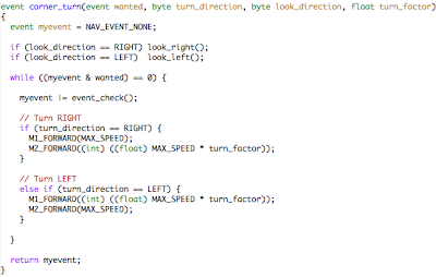
To solve the above scenarios it was easiest to stitch together a discrete set of motion behaviors, one of which is a constant radius turn. That way Pokey can follow the wall (another motion behavior) until it isn't there, and execute a constant radius turn around the corner. Each discrete motion can be independently tuned and life is happy. But how to make the robot trace a constant radius turn regardless of speed ... or battery charge?

I wondered if the ratio of the distances traveled by each wheel in a turn might also be the ratio of PWM signals applied to each motor. This assumes some things that I didn't want to noodle over. So I just tried it by varying pwm of one motor while setting the pwm of the other motor as a ratio of the first:

Close enough for government work as they say.

One can figure out the distance each wheel will travel on a turn of radius r, given a robot of track width w. Keeping it simple, measure r as the radius of the circle scribed by the inner wheel. Circumference, as every person on the street knows, is 2r * pi. So the outer wheel circle's circumference is 2(r+w) * pi.

Take the ratio of these, simplify algebraically (1+w/r), plug in w, and then you can either make a function that takes r as an argument and spits out the ratio, or manually start plugging in various values of r to build a table and make an interpolation/lookup table. Instead I just created a function for turning within nav.c where you supply the ratio (turn_factor) and I chose a hardcoded value when calling it from the main routine. Sloppy, but it worked. Incidentally the nav.c module holds all the lower level discrete behaviors: wall following, going straight, and turning.

You give the routine what direction to turn (LEFT or RIGHT -- constants) and what direction to point the IR ranger array (LEFT or RIGHT again) -- look_direction. Then you tell it what events make it stop (wall found, floor mark found, etc.)

Ideally it would be more elegant to choose a wall following distance (maybe self calibrating by reading distance to wall at the start) and set the turn radius to maintain that distance. Also, to keep the average robot speed constant for smoother looking motion, figure out the radius to the center of the robot and vary both motor PWMs. If you simply reduce the inner motor's power, the robot slows down slightly on turns, but at least this looks more natural than speeding up around turns.

Sunday, June 8, 2008

Firefighting Part II

The date is set! July 12 is the date of the next chapter in the autonomous robot firefighting saga! SHARC is putting on the contest this time. Can't wait to give it another go. Pokey is looking forward to a chance at redeeming himself from his embarrassing defeat in Ft. Collins.

As before, time is the enemy. School's back in swing (I thought I got the summer off, but noooo) and I have to get the Jeep ready for a big trip to Ouray by July 16. So fine tuning Pokey may be a bit tough to squeeze in, but hey, what else is new?

Tuesday, April 29, 2008

Pokey's Famous!

If you check out the latest issue of Robot Magazine you'll find that the Fort Collins robot firefighters are now famous! Pokey has his picture in the magazine, too ... along with some goofy guy.

Great articles by George M on the contest and his winning robot. Pokey's real glad to be in the magazine... but he wants a rematch!

I've been busy with my Jeep, work, and midterms, but when I get a second I'll share some more about Pokey's software. Stay tuned...

Sunday, April 13, 2008

Pokey's Software: Part 2

Most of the entrants used dead reckoning to navigate the firefighting maze, using Lego NXTwheel encoders built into the motor modules. The dimensions and layout of the maze are known (approximately) beforehand. Note that if you build the maze it doesn't quite look like the drawing.
Pokey was designed to run through the maze without using dead reckoning. Instead, the little robot looks for what I call "events" such as the appearance of a wall to the left or right. The disappearance of the wall on the right or left. Detecting a floor mark. Of course these events are based on lower level sensor code that we'll get to in future posts.

Most importantly, navigation relies very heavily on good wall following because staying oriented to a wall means Pokey knows where he is in his predictable little world. And, in fact, poor wall following performance resulted in his humiliating defeat. :) But more on the low level stuff later. Here's a rundown on the high level event based navigation functions in
nav.c

First off, here's the code that gets Pokey from home circle to the floating room. This code is in the main module, sparky.c

//////////////////////////////////////////////////////////////////////
// Home to Room A //////////////////////////////////////////////////////////////////////
go_straight(NAV_EVENT_WALL_HERE, LEFT);
wall_follow_left(NAV_EVENT_WALL_GONE);
myevent = corner_turn(NAV_EVENT_FLOOR|NAV_EVENT_WALL_FOUND, LEFT, LEFT, TURN_FACTOR * 0.80);
if ((myevent & NAV_EVENT_FLOOR) == 0) {
wall_follow_left(NAV_EVENT_FLOOR|NAV_EVENT_FRONT);
}
// Only way to align to the wall, for now
wall_follow_left(NAV_EVENT_FRONT);
stop_moving(); // Don't delete this you goon!

Pokey wants to follow the wall for the floating room to his left. But that wall doesn't appear right away, so Pokey drives forward looking for the wall to the left. His ranger array points left (second parameter below) and he takes off...

go_straight(NAV_EVENT_WALL_HERE, LEFT);

This routine drops out as soon as the wall is found. Now all he has to do is follow the wall until it disappears again.

wall_follow_left(NAV_EVENT_WALL_GONE);

Now he knows that he's in the middle of the maze and all he has to do is turn left into the first room using a constant radius turn (yes, we could use wall following but I found my way was easier to predictably achieve the proper distance once the robot has turned through 180°).

myevent = corner_turn(NAV_EVENT_FLOOR|NAV_EVENT_WALL_FOUND, LEFT, LEFT, TURN_FACTOR * 0.80);

Once Pokey either (a) crosses the floor marker at the door threshold or (b) finds the wall to the left after having made his 180° turn, we move onto the next step. If we still haven't found the floor marker, well, let's find it:

if ((myevent & NAV_EVENT_FLOOR) == 0) {
wall_follow_left(NAV_EVENT_FLOOR|NAV_EVENT_FRONT);
}

Ok, now Pokey knows he's in the room and that the wall is to the left. Pokey can then orient himself square to the room by relying on wall following that left wall until he gets to the corner-- when a wall appears dead ahead.

wall_follow_left(NAV_EVENT_FRONT);

Now Pokey can scan the room in a predictable fashion (more on that later), winding up either pointed at the candle if there is one, or pointed 180° opposite of how he came in--almost perfectly to leave the room. And since he's in the corner, he has a good stretch of wall to follow to reorient himself perfectly on the way out of the room. This is the same approach I used for every room.

That's the theory, but if you look at the video you'll notice he never makes it to the corner. Pokey doesn't straighten out fast enough after detecting the wall to the left and ends up continuing his turn until he is pointing at a sharp angle into the left wall. He sees the left wall in front of him and mistakes that for being in the corner. Oops.

Fortunately, the scanning routine works so well at orienting him that he's still able to navigate out of the room to the next one at least some of the time.

stop_moving(); // Don't delete this you goon!

During testing I would add stop_moving() calls to pause him at various places in the code so I could visibly troubleshoot what was happening. I'd forget and take out this call, too, and so he'd enter the room and run smack into the corner wall. So I wrote myself a little reminder.

From
event.h here are the nav events

#define NAV_EVENT_NONE 0x00 // disables the event check
#define NAV_EVENT_WALL_GONE 0x01 // wall disappears
#define NAV_EVENT_FRONT 0x02 // wall appears in front
#define NAV_EVENT_FLOOR 0x04 // floor mark detected
#define NAV_EVENT_WALL_FOUND 0x08 // wall appears
#define NAV_EVENT_THIN_WALL 0x10 // unused, unneeded
#define NAV_EVENT_SHORT_FRONT 0x20 // wall close in front
#define NAV_EVENT_WALL_HERE 0x40 // wall close
#define NAV_EVENT_ALL 0xFF // all events, unused for now

The navigation event routines take one of these events to "watch for" and once found they drop out. The event type is a bit field, each bit corresponds to an event. So your routines can report multiple events at the same time. Each one of those nav event routines calls this one to watch for events. I threw in some addition comments:

event event_check(void)
{
event myevent = NAV_EVENT_NONE;

get_distances();

// Ranger pointing right?
if ( Pointing == RIGHT ) {

// Is the wall within wall following range?
// do we need to add a little fudge factor to distance?
if (distance_right <>
myevent |= NAV_EVENT_WALL_FOUND;

// Has the wall gone away?

else if (distance_right > 550.0)
myevent |= NAV_EVENT_WALL_GONE;
}

// if ranger is pointing left
else if ( Pointing == LEFT ) {
// Is the wall within wall following range?
// do we need to add a little fudge factor to distance?
if (distance_left <>
myevent |= NAV_EVENT_WALL_HERE;

if (distance_left <>
myevent |= NAV_EVENT_WALL_FOUND;

// Has the wall gone away?
if (distance_left > 550.0)
myevent |= NAV_EVENT_WALL_GONE;
}

// Object ahead, probably at end of hall or something
if (distance_front <>
myevent |= NAV_EVENT_SHORT_FRONT;
}

// this number is kind of fudged, trial and error

if (distance_front <> myevent |= NAV_EVENT_FRONT;
}

// Crossed over something white
if (floor_detected()) {
myevent |= NAV_EVENT_FLOOR;
}

return myevent;
}

You can see there's some dependency on the lower level sensor routines (ranger, floor sensor). Anyway, here's an example of one of the nav event routines:

event wall_follow_right(event wanted)
{
event myevent = NAV_EVENT_NONE;

look_right(); // point the ranger right

// drops out when the desired event is found
while ((myevent & wanted) == 0) {


// find out the distances
range_error = target_distance - distance_right;

range_error_rate = last_range_error - range_error;

// wall correction is a PID type routine based on
// current distance error and rate of change of error
steer = -(WALL_CORRECT());


// limit steering, or if we get too far away the bot will just spin
if (steer < -30) steer = -30;

if (steer > 30) steer = 30;

// record error statistics
last_range_error = range_error;

move_forward(MAX_SPEED, steer);

// Add discovered events to myevent
myevent |= event_check();

} // while

return myevent;
} // wall_follow_right

There's plenty more I could talk about but I don't want a 50 page post, either. For example, momentum and stopping distance: the threshold for detecting the front wall has to depend on speed.

The code has plenty of opportunity for improvement and generalizing to account for different speeds, battery voltages, etc. Reworking the wall following to incorporate constant radius turns would be swell.

Hopefully you get the gist, and I hope you found this useful.

Wednesday, April 9, 2008

Pokey's Software

Jim of roboRobert had requested to see Pokey's code. Ok, here it is! This version is a current development snapshot. I chose to share this newer version because it is organized better than the competition code, which got messier as the deadline got nearer. :)

PokeySource20080409.tgz

Below is an overview of the code and how it's organized. The diagram shows the main dependencies as well. The software is organized into layers and modules, with the highest layer at the top of the diagram.

The software is written in C and was ported from code used to run Sparky (hence the sparky.c main module). The modules are implemented---in most cases---with both a C module and a header file to describe external interfaces. There are some global variables representing robot status accessed across modules.

I'll go into more detail on some modules in subsequent blog posts. (If there's anything you want to know, feel free to ask).

Sunday, March 30, 2008

Robots in Art

Back in college I and my best friend, Paul Potts, started talking about building a robot. We never did but we came up with a lot of fun ideas.

Paul is an artist and has had a lot of showings locally and is always coming up with some new creative idea. Here's his latest-- robot paintings!


Thursday, March 27, 2008

Say What?

Here's how to interface an ancient, 80's era, General Instruments SP0256-AL2 speech synthesizer chip to a Basic Stamp 2 so you too can give your robot the gift of virtually unintelligible, vintage, synthetic speech! (Listen closely to the audio clip and you can almost make out, "Hello world")

Audio Clip

Data Sheet:
See previous SP0256-AL2 post to download the data sheet.

Circuit Diagram:
sp0256-al2.sch


Note: the LM386 amplifier circuit provided in Robot Builder's Bonanza just wouldn't work. It differed slightly from the one presented in the data sheet. The data sheet circuit is pictured above, but with the addition of a giant 100uF power decoupling cap; the LM386 was apparently drawing enough current with the speaker attached to cause the BS2 to reset similarly to prior motor control problems. A somewhat smaller cap doesn't seem to work -- more investigation needed. The potentiometer above is actually not installed yet; a resistor is in place to prevent clipping that was showing up on the o-scope.

The Code:
SP0256AL2.bs2

' {$STAMP BS2}

' {$PBASIC 2.5}

' SP0256-AL2 Speech Chip
' Control Code

' Text: HELLO WORLD.
' Phoneme: HH EH LL AX OW (PAUSE) WW ER1 LL PA2 DD1 (PAUSE)
' Octal: 033 007 055 017 065 003 056 063 055 001 025 004

' Dec: 27 7 45 15 53 3 46 51 45 1 21 4

text DATA 27,7,45,15,53,3,46,51,45,1,21,4,0
ptr VAR WORD
char VAR BYTE

setup:
' P7 <- SBY ' P6 -> 'ADL
' P0-P5 -> Data

DIRL = %01111111
HIGH 6

ptr = text

PAUSE 2000

go:
' Set char to the next phoneme
' Send it

READ ptr,char
DEBUG DEC char, CR
IF char <> 0 THEN cont
END
cont:
GOSUB pout
ptr = ptr + 1
GOTO go

' Phoneme Output
pout:

' Now just set OUTL P6='ADL=1, (P0-P5) = phoneme byte

OUTL
= char | %10000000
DEBUG BIN ? OUTL

' And set P6='ADL=0 for 2usec to tell the chip to read
PULSOUT 6,1

' Wait for P7=SBY (standby) to indicate chip is done speaking
notdone:
IF IN7 = 0 THEN notdone
RETURN

Quick Code Explanation:
The data sheet goes into this in detail, but in short: the program puts the 6-bit phoneme data on data lines A1-A6, then pulses ^ALD low for a short time to let the chip know data is ready, then polls SBY until it goes high, then repeats until it runs out of phonemes.

That's it. This is just a prototype so there's lots more to do before this becomes useful. For example, wouldn't it be nice if a handy dandy AVR of some flavor could front end this chip and accept data over serial and/or I2C? Maybe even do true TTS?

Sunday, March 23, 2008

Circuit Design on Mac OS X

Circuit design is fine to do on paper for the simplest stuff but a CAD program is nice for everything else. I'd been using TinyCAD on my P3 400MHz, 128M desktop but am trying to move away from this glacially slow system, not to mention minimizing my exposure to Windows. :)

One good answer for Mac users is the free version of CadSoft Eagle running under the X11 windowing environment (follow the link to install X11). While it's not a seamless Aqua interface, it is actually a heck of a nice program once you get use to using it and it has an integrated PCB designer that works quite well. The user interface is a little bizzare, but with some practice I'm getting faster at drafting circuits. So far, the parts library seems to be pretty comprehensive, too.

If you want the app to show up in your Dock, you can write a shell script and use Platypus to create a wrapper application (may take several tries to figure it out) or try mine below which includes the shell script. Click on the link, save to disk, unzip, and copy the Eagle.app to /Applications. This app assumes the EAGLE-X11 folder is already installed in /Applications.

Basic Stamp Programming on Mac

With a pause between school "semesters," I've been neck deep in several projects. One of the smaller ones was assembling a Basic Stamp 2 prototype board that came with the book, 123 Robotics Experiments for the Evil Genius (TAB Robotics). This board features a spot for a solderless breadboard making prototyping 10x easier than the Parallax BS2 board I'd been using (let's just say that wire wrapping sucks).

In a never-ending quest to unshackle myself from Winderz, a Google search followed by a quick experiment revealed that one can program BS2 using my favorite operating system. How? Easy.
  1. MacBS2: This is the IDE. Not fancy but who cares? Download it here.
  2. Keyspan Serial Adapter or equivalent (e.g., Keyspan High Speed USB Serial Adapter ( USA-19HS ) from Amazon -- check to make sure this will work on the MacBS2 website).
After downloading MacBS2 read and follow the install instructions. You'll copy the application to the Applications folder. Using an administrator account, launch the application and when prompted, click to download & install the tokenizer library.

Install your Keyspan (or whatever) software, and plug it into the computer & proto board. Write a program. Click run. Et voilà! Enjoy the magic of BS2 on Mac OS X. :)


(To those who celebrate it with me, Happy Easter! Otherwise I wish you a Happy Sunday :))

Thursday, March 20, 2008

Firefighting: Video Clips

I'm hoping to get some more clips and different angles from those present, but for now here's some of the robots (including Pokey :)) from the Ft. Collins Robot Firefighting Competition:


Tuesday, March 18, 2008

Fan Motor Circuit

Thanks to Brij who pointed out some problems with Pokey's fan motor driver circuit that I threw together at the last minute. I stand corrected :)

Going to go back to the drawing board and pull out the old school textbooks. I pulled the original post for now.

UPDATE! I started a new series of articles on revising this fan motor driver using SPICE modeling.

Monday, March 17, 2008

Flame Sensor

Quite a few people have asked questions about Pokey's flame sensor (the big, cylindrical yellow and black thing in the picture). Here's the rundown.

First and foremost, the design uses infrared LEDs for sensing infrared radiation. Yes, that's right, LEDs. Of course LEDs emit radiation when voltage is applied, but a little known fact is that they also generate a voltage in the presence of radiation -- and specifically radiation in the frequency range that they emit. I tried UV LEDs but they weren't sensitive enough to detect UV output of a candle. The pile of IR LEDs I ordered happened to generate about 0.5V max when pointed at incandescent lamps, candles, etc.

The only problem? Range. By themselves IR LEDs are a bit too limited in range to provide a strong signal from across the largest of firefighting rooms. I had the idea of using some kind of optics to increase range and after some experimentation the solution was to use the reflector off of a $3.50 Eveready lantern flashlight with the LED replacing the bulb. Range was increased to at least 8' -- plenty.

This device has the added benefit of limiting field of view, making the sensor less sensitive to IR sources outside the arena, but very sensitive to candles within the regulation height range. I installed dual IR LEDs in the housing hoping to give the sensor directionality but this didn't work out. A single LED works just as well.


Finally, to give the MCU's Analog to Digital Converter (ADC) a little more voltage range to work with, the signal from each LED runs through half of a simple, single-source op amp amplifier (LM258 or equiv) as pictured above. The resistor and capacitor in parallel seemed to help stabilize the LED signal when I was experimenting, taking ADC readings directly from the LED.

I used aluminum tape to block off the sensor's view to the side, essentially improving the "peakiness" of the sensor's response when scanning a room, making it easier to pinpoint the direction of the candle.

Edit: Brij asked why not use an IR phototransistor or photodiode (see comments). At the start, I tried several different sensors, actually. The phototransistor was too sensitive; pegged out too easily. Didn't think to try a photodiode. The LEDs showed a fairly linear response, just enough sensitivity. In short, they work great!

Sunday, March 9, 2008

The Competition

Ended up leaving around 8:40 having just tested scanning for and extinguishing a candle in the living room. Arrived up in Ft. Collins by 10:10, with plenty of time to adjust floor sensors, test the robot in the arena and tweak code.

SHARC and FRR made a great showing with lots of competitors and spectators. The room began filling up with kids to watch the event. While all this was going on, my robot kept misbehaving right at the starting circle, making a left turn into the wall about 75% of the time. I couldn't figure it out.

Then my batteries died. While I swapped them out, the wires to my battery tray broke loose again! I had to jerry rig a solution: strip the wires and manually wrap them around the end terminals. Stressed out, fumbling around, trying to block out the noise and chatter of the crowd, I got that fixed and it held together for the rest of the competition. By now there was a good sized crowd of small spectators and quite a few adults as well.

My first run was a disaster. Even though the candle was in the first room in Pokey's list to visit, the robot careened off to the left again directly into a wall. Others in the competition had problems with navigation at first, too. Pokey went back to the bench for diagnosis. For some reason the IR rangers, which had been dead solid in every condition I'd tested, were giving jittery readings and popping above and below the threshold for detecting the presence of a wall. This tricked Pokey into thinking he was farther along on the course than he actually was. With new threshold values Pokey was ready for the 2nd run.

This time around the odds were seriously stacked against the little red robot. The candle was in one room he'd never made it to before was the one directly adjacent to the start position, the last one on the search path. Though Pokey got to both the first and second rooms, his poor wall following set him off in the wrong direction for room 3.

By this point, George had put out a candle with water, and Anthony did as well! Very awesome to see these robots working so well!

Back on the bench, I did some additional minor code tweaks and put Pokey on the home circle for the third and final trial. The candle was in the 2nd room on his itinerary so there was a good chance for success.

The timer started, Pokey was off. He made it into the first room flawlessly, scanned, then exited and made his turns into the second room, stopping a bit short, then he scanned... but missed the candle and left the room! My last minute coding of the scanning routine just wasn't solid enough yet. So close...

In the end, George took 1st and Anthony 2nd. Congrats to them and to all the competitors. It's not easy building a robot for a competition and everyone who fielded a machine can be proud of that accomplishment.

Heck even those who didn't field a machine but have a start on one ought to feel pretty good. And since SHARC is going to host a firefighting challenge in April we all get another shot at this. (Well, unless it happens on the same weekend as my trip to Moab for four-wheeling).

In the meanwhile, I'll share what I've learned, post up code and circuit diagrams and other fun stuff. Once I get all the video and pictures from folks I'll edit together a video and post that too.

Thanks to everyone who has been reading this saga, your support is much appreciated!