Monday, June 29, 2009

SPICE: Part 4

<< [Part 1 2 3 4 5] >>

To continue where we left off, the current required to turn on the TIP3055 NPN power transistor to run Pokey's firefighting fan motor was higher than the 40mA maximum that the ATmega168 can handle.

To get around that, let's add a switching transistor to provide that drive current. In turn, this new resistor will require far less base current signal to activate.

This time, let's use a PNP transistor, a 2N3906, to activate the power transistor. PNPs are turned off, that is, put into the cutoff region when the base voltage is high: positive with respect to the collector and emitter voltages, reverse biasing both junctions. Active mode occurs when the base voltage is negative with respect to the emitter voltage, forward biasing that junction, but positive with respect to the collector (reverse biased). Finally, saturation, what we need to achieve to turn the transistor on like a switch, occurs when both junctions are forward biased; the base voltage is negative with respect to both C and E. (Source).

If we put the load for the PNP between the collector and ground, and tie the emitter to our voltage source, we can easily set a base voltage less than the collector by tying it to ground through a resistor.

As with the NPN, we have to select this base resistor, RB, to allow an amount of base current to flow that is 2-10 times the threshold required for the transistor to leave the active mode, given the target collector current, IC.

Note that the current will be flowing out of, rather than into, the base of the PNP. Here's the circuit diagram.
We'll use a simple voltage source for now to simulate the digital logic signal but eventually we'll replace it with a PULSE source again.

Worth mentioning, it might not be a bad idea to include a pull-up resistor (say, 10kΩ) from node 10 to +5V. That way the MCU doesn't have to hold a logic high on the line at all times, like during reset, and when it does sink current, the pull-up isn't adding much on top of IB1.

First, recalculate RB2 to account for the VCE1 drop across the new transistor.

RB2 = (VCC-VCE1-VBE2)/IB2 = (5 - 0.3 - 0.7)/48mA = 83Ω

Since we're given Q1's ICsat1 already, all that's needed is to calculate the required IB. Note VCB=0 in saturation. Looking at the datasheet for the 2N3906, hFE=60 at ≈48mA.

IB1sat = IC1sat ÷ hFE = 48mA ÷ 60 = 0.8mA
IB1 = IB1sat • 10 = 8mA

So we can find out Q1's base resistor.

RB1 = VB1/IB1 =(VCC-VBE1)/IB = (5 - 0.7)/8mA = 538Ω

With all that, here's the SPICE file: ex4.cir using, for now, a 5V source for the signal to permit steady state (OP) analysis. With 5V fed to the PNP base, the transistors are off.
v(4) = 9.000000e+00 [Vce2]
i(vm) = 3.730349e-11 [Im]
v(5) = 8.760559e-02 [Vbe2]
i(vb1) = 2.715710e-14 [Ib1]
i(vb2) = 4.940826e-12 [Ib2]
Now, tying RB1 to ground we get:
v(4) = 1.226405e-01 [Vce2]
i(vm) = 4.931866e-01 [Im]
v(5) = 7.614809e-01 [Vbe2]
i(vb1) = -7.48235e-03 [Ib1]
i(vb2) = 3.564787e-02 [Ib2]
So current through the 'motor' is still ok, but notice that the base current driving the TIP3055 into saturation is about 20% lower than calculated and the Q1 base current isn't quite high enough either by about 5%. I suppose this is a result of the various estimations made in the calculations (e.g., VCEsat, VBE, etc.) versus what the datasheet shows. I'll update this article when I get a chance to sort it out fully.

But thankfully there's circuit simulation software to help play what-if games. A little experimentation with SPICE suggests that using a smaller base resistor (such as 400Ω) on Q1 will drive it, and in turn Q2 a little harder, with IB2 closer to the original desired amount.
v(4) = 1.177275e-01 [Vce2]
i(vm) = 4.934596e-01 [Im]
v(5) = 7.675888e-01 [Vbe2]
i(vb1) = -9.88113e-03 [Ib1]
i(vb2) = 4.700498e-02 [Ib2]
Of course in the real circuit one would use resistors of standard E12 values like RB1=390Ω and RB2=82Ω. As for driving this circuit with an MCU, the ATmega168 should have no trouble sinking the approximately 10mA of current from Q1's base.

In the next part in the series, I want to cover another SPICE feature, subcircuits, which encapsulate entire circuits behind a few input/output pins. There's a really clever approach to modeling motors, both mechanically and electrically, in SPICE which is what I'll use as the subcircuit. More soon!

<< [Part 1 2 3 4 5] >>

Tuesday, June 23, 2009

SPICE: Part 3

<< [Part 1 2 3 4 5] >>

Since the last article, part 2, I've been refreshing my memory on the topic of BJTs, cracking open my old college text, Microelectronic Circuits (Sedra, Smith), which I recommend as a good reference. There's a newer, way more expensive edition available (Microelectronic Circuits Revised Edition) but I think the 2nd edition is good enough.

At any rate, I wanted to start from scratch with the motor, and work outward from there to try and come up with a better circuit.

The Motor

For now, I'll continue using a basic resistor which is probably good enough for steady state (operating point) analysis. I found a facsimilie of the motor I'm using. The Mabuchi FK-180SH-14800 is a 12V motor of approximately the same size that uses 0.34A at maximum efficiency. Let's say my motor uses 0.5A at 9V. In which case the motor's steady state resistance would be about 18Ω. So how do we use the TIP3055 to run this motor? (Yes, I realize that using a 15A transistor to drive a 0.5A load is overkill... it was just what I had on hand at the time)

Transistor Saturation and Topology


We want to drive the TIP3055, an NPN Bipolar Junction Transistor (BJT), into saturation. In this state, collector current, IC, is essentially at a maximum despite any additional base current, IB, that we will want to add. As you might expect, then, BJTs enter saturation mode when

IB > IC ÷ ß

Typically one wants to drive the transistor well into saturation by making sure IB is 2-10 times the saturation value of IB. This is called the overdrive factor. Ultimately, we control the amount of base current by selecting the an appropriately sized base resistor, RB.

Note that if we stick the motor on the transistor's emitter, then it limits how much extra base current we can supply at the base. Instead, it is typical practice to place the resistive load of the motor bewteen the voltage source and the collector terminal. That way the only resistance limiting IB is the base resistor.

Selecting the Base Resistor

Our first step is to determine the saturation collector current, ICsat. To do this, we analyze the circuit (right) using Kirchoff's Voltage Law where we set VBE=0: ICsat = (VCC - VCEsat) / RM ; then calculate IBsat = ICsat ÷ ß and finally, select our desired IB = 10•IBsat

The book says to assume VCEsat is approximately 0.3V. Upon looking at the data sheet for the TIP3055, actually varies depending on the IC but as long as we estimate VCEsat on the low side, it seems to me that we'd end up with a larger IB which will only ensure we are driving the transistor well into saturation.

The value of ß, as I understand it, is equal to hFE (DC current gain) for a given IC, as specified by the data sheet. Looking up an IC of 0.5A, hFE = 100. Working the numbers, we get

ICsat = (9 - 0.3) / 18 = 480mA
IBsat = 480mA ÷ 100 = 4.8mA

And with an overdrive factor of 10,

IB = 10•4.8mA = 48mA

Now that we know what IB we're looking for, we simply solve for RB = (VCC - VBE) ÷ IB. The book says to use VBE = 0.7V. We get:

RB = (9 - 0.7) ÷ 48mA = 173Ω

But I want to drive the circuit with a 5V signal from a microcontroller (the ATmega168) Hooking RB to a 5V source instead of 9V we get:

RB = (5 - 0.7) ÷ 48mA = 90Ω

SPICE Model

So let's whip up a SPICE model and see if that matches up with what we've done so far. Here's the circuit (right) with the nodes labeled. We're using a 0V supply, VM, to measure IC and similarly the 0V supply, VB, measures IB. We'll continue to use the same TIP3055 model as before and we'll set up the resistors per calculations (RB=90Ω and RM=18Ω)

This time, let's do an operating point analysis. As mentioned previously, the OP command tells SPICE to find out the steady-state of the circuit and the PRINT commands specify what variables to print. We are interested in the base voltage, V(5); the collector-emitter voltage, V(3); and of course the base current, I(VB) and collector current, I(VM).

Below is the SPICE deck to accomplish all that.
Motor driver
V9 1 0 9.0
V5 2 0 5.0
RM 1 3 18
VM 3 4 0
Q1 4 5 0 TIP3055
VB 6 5 0
RB 2 6 90

.MODEL TIP3055 NPN(Is=457.5f Xti=3 Eg=1.11 Vaf=50
+ Bf=156.7 Ise=1.346p Ne=1.34
+ Ikf=3.296 Xtb=2.2 Br=7.639 Isc=604.1f Nc=2.168
+ Ikr=8.131m Rc=91.29m Cjc=278.7p Mjc=.385 Vjc=.75
+ Fc=.5 Cje=433p Mje=.5 Vje=.75 Tr=1.412u Tf=37.34n
+ Itf=35.68 Xtf=1.163 Vtf=10 Rb=.1)
.control
op
print v(4) i(vm) v(5) i(vb)
.endc
.end
And when we run it, we get numbers that actually kind of match what we expected. Cool. Our IC is about 490 mA, IB is 47 mA and VBE is about 0.77 V. It's not exact because we were using some estimates, but it's close enough.
MacSpice 45 -> source Macintosh\ HD:Desktop:ex3.cir

Circuit: Motor driver

v(4) = 1.177197e-01
i(vm) = 4.934600e-01
v(5) = 7.675994e-01
i(vb) = 4.702667e-02
Note that the ratio of IC to IB is 10, considerably less than a ß (hFE) of 100 that we'd expect in active mode for a collector current of about 0.5A. In other words, we're forcing in extra base current without any appreciable gain in collector current. That's saturation.

Incidentally, if you want to see what happens when the 5V signal is switched off, just revise the deck to tie RB to ground. Here's what happens to the voltages and currents:
v(4) = 9.000000e+00
i(vm) = 2.201261e-11
v(5) = 9.757939e-10
i(vb) = -1.08422e-11
Base and collector current are negligible and there's no voltage drop across RM or RB. In a word, the transistor is off. Just what we expected.

Too Much Signal Current

One little gotcha. As I mentioned, I want to drive this circuit with an ATmega168 which is limited to 40mA per data pin, according to the datasheet. So in the next article I'll incorporate a second transistor to drive the first and add that to the SPICE model above and see what we can come up with.

<< [Part 1 2 3 4 5] >>

Friday, June 19, 2009

SPICE: Part 2

<< [Part 1 2 3 4 5] >>

Last we left off, I wanted to use SPICE to model my fan driver circuit and help me find ways to improve it. The motor was intended to run on 9V but the Orangutan LV168 driving it was only delivering a 5V logic high signal. The circuit I threw together at the last minute only delivered a fraction of the 9V supply voltage to the motor.

Here's the circuit diagram, drafted in CadSoft Eagle on the Mac. I've edited it with a graphic editor to add a couple of SPICE elements and node label numbers (in green) to each of the nodes to make it easy to create the SPICE file.

Also, adding onto what we talked about in the first article, Part 1, our new SPICE model will include three new circuit elements we haven't talked about yet.
  • BJT transistors and transistor models (Q1, Q2)
  • A special "pulse" voltage supply (VR) to simulate 5V signal pulses from the MCU
  • A zero-volt power supply (VM) used to measure current through the "motor"
Transistors and Models

First let's talk about transistors and models. Using SPICE you can model semiconductors--diodes and transistors--of various types, the properties of which you specify in a model statement. These models are usually available from manufacturers as well as online for more common parts.

In the diagram you can see I am using an 2N2222A and a TIP3055 transistor. I searched the web and found a model for a 2N2222 (close enough; we could try to find a 2222A if we really needed to) and the TIP3055. Here they are. The "+" character is a line continuation so you can put the model statements on more than one line.

.model 2n2222 npn (is=19f bf=150 vaf=100 ikf=0.18 ise=50p
+ ne=2.5 br=7.5 var=6.4 ikr=12m isc=8.7p nc=1.2 rb=50 re=0.4
+ rc=0.3 cje=26p tf=0.5n cjc=11p tr=7n xtb=1.5 kf=0.032f af=1)

*.model TIP3055 ako:NSC_4A NPN() ; case TO-220 (s)
.MODEL TIP3055 NPN(Is=457.5f Xti=3 Eg=1.11 Vaf=50 Bf=156.7 Ise=1.346p Ne=1.34
+ Ikf=3.296 Nk=.5961 Xtb=2.2 Br=7.639 Isc=604.1f Nc=2.168
+ Ikr=8.131m Rc=91.29m Cjc=278.7p Mjc=.385 Vjc=.75 Fc=.5 Cje=433p
+ Mje=.5 Vje=.75 Tr=1.412u Tf=37.34n Itf=35.68 Xtf=1.163 Vtf=10
+ Rb=.1)


(For whatever reason, MacSpice didn't recognize the Nk parameter, in red above, and ignored it). When you add a BJT circuit element, you specify it as:
     Qname NC NB NE Mname
where Qname is the name of the transistor (Q1, Q2, QA, etc), NC is the Collector node, NB is the Base node, and NE is the Emitter node. Mname is the model name, like TIP3055 if you're using that model from above.

You can model BJTs, either NPNs or PNPs. You can model other transistors too. MacSpice lets you specify a number of BJT parameters in your model, such as:
  • BF: Ideal maximum forward beta
  • VAF: Forward early voltage
  • ISE: B-E leakage saturation current
  • NE: B-E leakage emission coefficient
  • RB: Zero bias base resistance
  • RE: Emitter resistance
  • RC: Collector resistance
  • TF: Ideal forward transit time
  • And much more...
A complete list of parameters for transistors and diodes can be found in the MacSpice (or any SPICE) user guide. That way, if you cannot find a SPICE model ready-made to cut-n-paste for your transistor, but you can find these parameters in the data sheet, you can create a model from scratch. But probably most of the time you will just use a model already created for a standard component that you're using.

Measuring Current

Now, as to the two new voltage supplies, the easy one is the 0V supply. In SPICE the only way to measure current is at/with a voltage supply; you cannot measure it through a resistor, for example. When I say measure, what I really mean is to have SPICE print or plot the values. We'll get into how to do that shortly.

Simulating MCU Signals

SPICE provides a PULSE type of voltage supply that allows you to specify a supply that has repeating output pulses. You do this by using the PULSE parameter when describing the value of a voltage supply:
     VIN 3 0 PULSE(-1 1 2NS 2NS 2NS 50NS 100NS)
The first two values are the initial and pulsed (high) values of the supply. In our case the LV168 spits out 5V signals so I used 0.0 and 5.0 here.

The next two parameters specify the rise and fall time of the pulse. I could go look that up but for now I just used 1 nanosecond, specified as 1ns.

The final two parameters are the pulse width and the period. I arbitrarily picked 100ms for the pulse width and doubled that for the period to get a nice square wave output. Depending on how the simulation looks I may extend that time.

The SPICE Deck So Far

SPICE files containing circuit specifications are called "decks". Anyway, once you enter in the transistors and voltage supplies, in addition to the resistors and capacitors, here's what you have so far.

Crappy fan motor driver
* Fan power supply
V1 1 0 9.0
* Simulates MCU FAN_ENABLE signal
VR 5 0 PULSE( 0.0 5.0 5ms 1ns 1ns 100ms 200ms )
* 0 volt for measuring motor current
VM 2 6 0
Q1 1 4 3 2N2222
Q2 1 3 2 TIP3055
RM 6 0 2
C1 1 0 100U
R1 5 4 47
* model for a 2n2222 transistor
.model 2n2222 npn (is=19f bf=150 vaf=100 ikf=0.18 ise=50p
+ ne=2.5 br=7.5 var=6.4 ikr=12m isc=8.7p nc=1.2 rb=50 re=0.4
+ rc=0.3 cje=26p tf=0.5n cjc=11p tr=7n xtb=1.5 kf=0.032f af=1)
*.model TIP3055 ako:NSC_4A NPN() ; case TO-220 (s)
.MODEL TIP3055 NPN(Is=457.5f Xti=3 Eg=1.11 Vaf=50 Bf=156.7 Ise=1.346p Ne=1.34
+ Ikf=3.296 Nk=.5961 Xtb=2.2 Br=7.639 Isc=604.1f Nc=2.168
+ Ikr=8.131m Rc=91.29m Cjc=278.7p Mjc=.385 Vjc=.75 Fc=.5 Cje=433p
+ Mje=.5 Vje=.75 Tr=1.412u Tf=37.34n Itf=35.68 Xtf=1.163 Vtf=10
+ Rb=.1)

Transient and Operating Point Analysis

Now that we have a circuit to analyze, how do we analyze it? I mentioned last time that you can do Operating Point (steady state) analysis or you can do Transient analysis. You can print out voltage and current values, or you can plot them graphically.

At the end of the deck, you can tell SPICE what to do with the circuit. Use the command .OP for operating point analysis or the .TRAN command for transient analysis. For transient analysis you specify, at a minimum, the time step (TSTEP) and stop time (TSTOP) parameters, like .TRAN 100ms 1000ms for a 100ms step time stopping after 1 second.

To get SPICE to plot the results graphically when you load the file, your deck needs to include interactive controls, bracketed by .CONTROL and .ENDC statements. In our case we want to plot the voltage at node 2 and the current through our 0V measurement supply VM:

.control
plot v(2) i(vm)
.endc

The Finished Deck

Finally every deck should have a .END statement at the ... well... end. Putting it all together, here is our deck for the crappy fan motor driver.

Crappy fan motor driver
* Fan power supply
V1 1 0 9.0
* Simulates MCU FAN_ENABLE signal
VR 5 0 PULSE( 0.0 5.0 5ms 1ns 1ns 100ms 200ms )
* 0 volt for measuring motor current
VM 2 6 0
Q1 1 4 3 2N2222
Q2 1 3 2 TIP3055
RM 6 0 2
C1 1 0 100U
R1 5 4 47
* model for a 2n2222 transistor
.model 2n2222 npn (is=19f bf=150 vaf=100 ikf=0.18 ise=50p
+ ne=2.5 br=7.5 var=6.4 ikr=12m isc=8.7p nc=1.2 rb=50 re=0.4
+ rc=0.3 cje=26p tf=0.5n cjc=11p tr=7n xtb=1.5 kf=0.032f af=1)
*.model TIP3055 ako:NSC_4A NPN() ; case TO-220 (s)
.MODEL TIP3055 NPN(Is=457.5f Xti=3 Eg=1.11 Vaf=50 Bf=156.7 Ise=1.346p Ne=1.34
+ Ikf=3.296 Xtb=2.2 Br=7.639 Isc=604.1f Nc=2.168
+ Ikr=8.131m Rc=91.29m Cjc=278.7p Mjc=.385 Vjc=.75 Fc=.5 Cje=433p
+ Mje=.5 Vje=.75 Tr=1.412u Tf=37.34n Itf=35.68 Xtf=1.163 Vtf=10
+ Rb=.1)
.tran 10ms 1000ms
.control
plot v(2) i(vm)
.endc
.end

The Results!

And here is the graphical plot, showing the motor is only seeing 3.5V (red) and drawing a little over 1.5A (green). Remember that we are just representing the motor with a resistor, 2Ω in this case. We'll add a more complex, realistic motor model soon.

Next time I'll see if I can't use modeling to help improve upon the original design. We can try a few things in SPICE without having to breadboard them first.

<< [Part 1 2 3 4 5] >>

Tuesday, June 16, 2009

SPICE: Part 1

[Part 1 2 3 4 5] >>

The last couple days I've been learning how to use SPICE circuit simulation software and thought I'd share what I've learned.

SPICE, Simulation Program with Integrated-Circuit Emphasis, has been around for 30+ years and is still an industry standard for modeling circuits to see how they'll behave. It can do transient analysis, steady-state, AC small signal analysis, DC transfer function analysis. You can model numerous devices and print and plot the results of the simulation.

I've been using MacSpice for Mac OS X. The tool remains text based, but with some menu wrappers for a few functions.

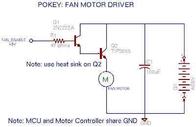
Revisiting Pokey's Fan Motor Circuit: You may recall the crappy, last minute, motor driver circuit I threw together for Pokey, my firefighting robot. I want to use modeling to analyze the existing circuit and to help me come up with a better design.

But first, let's talk about SPICE. The MacSpice website has good documentation:
I found the following websites helpful, too:
Ok, onto the modeling. First I have to draw the old motor circuit. Then I have to convert that into a SPICE circuit description file. The description file lists each of the components, and what nodes the components are connected to. Here's the old circuit diagram.

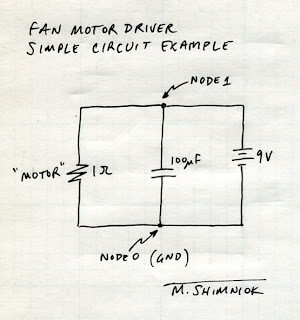
Let's start with a much simpler circuit; we'll ditch both transistors and represent the motor as a simple resistor, tying it directly to 9V and GND. We'll keep the capacitor and 9V battery. Here's the circuit with the nodes labeled to make it easier to enter into a SPICE file.

Note that the GND node must ALWAYS be node 0 or you will get errors like "Warning: singular matrix", "Warning: source stepping failed", "Warning: gmin stepping failed", "No convergence in DC analysis", and "failed to converge". I spent about 2 hours trying to find out that I simply needed to number the ground node zero!!

Let's start with the voltage supply. A simple DC supply is described by Vname n+ n- value where n+ is the positive node, n- the negative node and value is the DC volts value.

Next, there's the "motor" resistor described by Rname n+ n- value where value is the resistance, let's say 1Ω.

The capacitor is described by Cname n+ n- value as you might expect. (It has another option, the initial voltage, but we'll ignore that for now)

Note that SPICE can represent kilo, mega, milli, nano, pico, micro, etc. with a code (K, Meg, M, N, P, U, etc., respectively) so our 100µF cap value is represented by 100U. Here's the SPICE file. Comments are preceded by an asterisk (*)

Example SPICE FILE
* Voltage supply is across nodes 1 and 0
V1 1 0 9.0
* Resistor in parallel on nodes 1 and 0, 1 ohm
R1 1 0 1
* Capacitor in parallel on nodes 1 and 0, 100uF
C1 1 0 100U


The first line of a SPICE file is always the title. Don't forget that or the component you put on the first line will be missing when SPICE analyzes the circuit!

So, create the file, example1.cir, and put the above text in it. You can load it into MacSpice (or whatever SPICE program you use) and analyze it. Here's what I got:

MacSpice 8 -> source #
User selected - example1.cir

Circuit: Example SPICE FILE

MacSpice 9 -> op
MacSpice 10 -> print v(1)
v(1) = 9.000000e+00
MacSpice 11 -> print i(v1)
i(v1) = -9.00000e+00
MacSpice 12 ->

You may wonder what the op, and print statements do. The op command tells SPICE to analyze the operating point (steady state). The first print statement above displays the voltage at node 1, v(1), which is 9V as we would expect. The second displays the current supplied by the v1 supply, i(v1).

That's good enough for now. In the next article I'll add more complexity to the model more complicated and do more with the analysis of the circuit.

[Part 1 2 3 4 5] >>

Tuesday, June 2, 2009

DIY Dim Bulb aka Poor Man's Variac

This isn't strictly robotics-related but in case you're into repairing old radios, stereos, oscilloscopes, etc., you might find this handy.

It's called a poor man's variac and there are no doubt myriad other websites on this topic. I found some plans for this on Audiokarma.org.

Standard disclaimer: of course you'll need to verify these instructions to make sure everything is safe and sound.

Whereas variacs are variable transformers that limit line voltage to your device under test, the poor man's variac, or dim bulb tester, uses a light bulb to limit current.

The light bulb is wired inline with the electronic device, acting as an inline resistor. But it's better than a simple resistor because light bulb resistance increases when the filament heats up.

When there's no short in the device, some limited current is drawn through the light bulb but not enough to significantly heat the filament so resistance stays relatively low (the device will still see reduced line voltage). But if there's a short in the device it has near zero resistance and wants to draw as much current as possible. The bulb is allowed to light and its resistance climbs, reducing the maximum current that can flow through the damaged equipment.

Hopefully this prevents the magic smoke in your device under test from escaping :)

Here are the parts I used to build it
  • Lightbulb shield to protect against broken bulb and shocks
  • Standard outlet
  • Standard switch
  • Appropriate gauge household wire: white, black, about 6" each
  • A length of lamp cord of appropriate gauge (or use 3-wire cord)
  • Polarized plug (or use a grounded plug)
  • 2 gang box
  • A lamp bulb socket that accepts threaded rod and shield
  • Lamp threaded rod and nut hardware
  • 40 or 60W bulb (lower wattages allow less current)
Wire up the hot side from the plug wire (narrow prong; see info on polarized plugs) to one terminal of the switch. Wire the other terminal to one terminal of the lamp socket. Wire the other lamp socket terminal to the hot side of the outlet. Wire the neutral side of the plug wire (wide prong) to the neutral side of the plug.

Drill a hole in one side of the 2 gang box big enough for the threaded rod. Install this, and clamp to the plastic housing with two nuts. Screw the threaded rod into lamp housing. Install the switch and outlet into the box. Attach the shield around the bulb for safety's sake!!

That is all there is to it! Now plug in your tester and plug a stereo or oscilloscope and flip the switch. The bulb will probably glow brighter at first due to inrush current filling the large capacitors in the power supply and then will grow dim or simply not glow at all if everything is ok. You can start with lower watt bulbs and work your way up to 100W at which point you are probably ok to plug the unit into the wall directly.