The concept is a drive sprocket for the elbow that shares the same rotational axis as the shoulder and its drive sprocket. The elbow drive sprocket in turn drives a sprocket in the elbow with the chain running through two arm parallel arm tubes. The sketch needs a little work. The shoulder's axle would have to ride on bearings, while containing bearings that support the inner elbow axle. A sprocket would be attached to each axle.
Why actuate the elbow this way rather than having a motor attached to the arm itself? So all the big arm motors could sit inside the chassis instead of adding weight and bulk to the arms. And center of gravity can be kept low. Is it workable, practical? I have no idea.
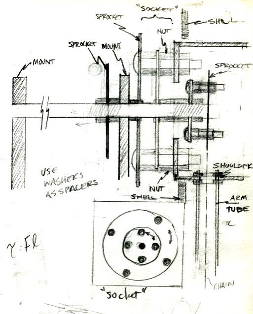 Never did try to make this. The other concept in play here was that the shoulder would be somewhat easy to remove, by undoing a few lug nuts similar to removing a tire. Speaking of automotive analogies...
This sketch got me to thinking about the many times in the intervening years that I've taken apart my Jeep's front hub and full floating axle assembly (see pic below). Maybe axle designs will be of interest to the robot designer...
The way a 4x4 floating front axle works is this. The tire is bolted to the hub. The hub (67) spins on the spindle (62) by way of inner and outer wheel bearings (65, 66). These bearings bear the weight of the vehicle, which is transferred through the suspension to the axle housing, to which the spindle is attached.
 Meanwhile, the spindle is just a tube and through it runs the axle shaft (56). A bearing inside the spindle (61) supports the axle shaft. The end of the axle shaft has splines cut into it. The inner surface of the hub has splines, too. A drive flange is a puck of steel with a hole in the middle. The hole has splines and slides onto the axle shaft splines. The outer edge of the flange has splines too and those engage the hub splines. But most 4x4s use manual locking "hubs" (73-76) instead of a drive flange so that the axle shaft can be engaged with the hub & rotor assembly (67) when in 4wd and disengaged when in 2wd.
Kind of an interesting concept that allows the axle tube, bearings, spindle to bear the weight of the vehicle, so that the only thing the axle shaft does is transfer torque. By contrast, in a semi-floating axle like you'd find on the rear of 1/2 ton trucks with "live" axles, the wheel bearings are pressed onto the axle shaft and ride on a race that is mounted in the axle tube.
 The axle shaft has a mounting flange to which the wheel is bolted. In other words, the weight is borne by both the axle tube and the axle shaft itself. This type of axle generally is able to carry less weight than a full floating axle of similar size because the axle takes on double duty.
So, that's 4x4 axles in a nutshell...
No comments:
Post a Comment
Note: Only a member of this blog may post a comment.