 |
| Heathkit IG-4505, photo from www.museudatecnologia.net.br |
I really would like an oscilloscope calibrator, like the Heathkit IG-4505, to tune up my 'scopes. Sure, I could spend the $30-60 on a used, pre-assembled specimen, even find an unassembled kit. In the meanwhile, I want to play around with the circuitry and possibly build my own from scratch. But how?
If you spend any time on Electro Tech Online, and if you're an old school digital logic kinda person like me, you quickly notice that the answer to all problems seems to be: "use a microcontroller." Ok, sure, a tiny little 8-pin DIP can easily solve a LOT of problems including this one and I may eventually build an MCU version of the calibrator.
Doing so misses out on they joy and thrill to be found in assembling a bunch of giant, antiquated PDIP logic ICs into something useful that requires no software and no PC (I can think of one blogger who would probably approve). Plus, a bunch of TTL ICs look cool on a breadboard. So today it's time to flash back to decades past when TTL ruled the world.
Rather than starting with a blank slate, an easier starting point is reverse engineering the Heathkit calibrator and emulating the circuit with similar ICs. I'll breadboard a prototype of the circuit to make sure this is going to work. The schematic can be found here. It comes in zip form, two pages.
Functionality
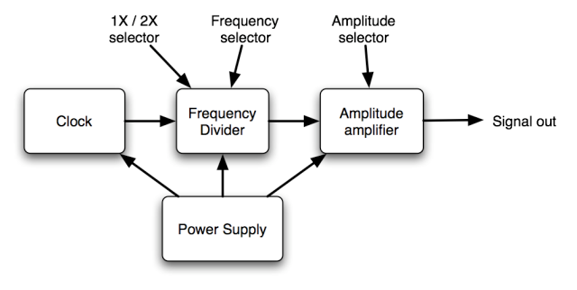
What does it do? The 4505 provides square wave output pulses at periods of 1uS, 10uS, .1mS, 1mS, 10mS, and 100mS. It also provides a feature to increase the periodicity of the signal by 2X and 5X. Lastly, output levels can be adjusted from 1mV to 100V in 10X steps. This functionality allows the technician to calibrate the scope's time base and vertical amplifier so it reads accurately. I put together a block diagram, below, which helps decompose the problem. We'll focus on the clock and frequency divider sections.
 Clock Circuit
The clock circuit in the IG-4505 circuit starts with a 4MHz crystal oscillator (see picture below, lower left, labeled 4MHz). This signal is then divided down to lower frequencies by TTL counters. Instead of a crystal, I happened to find some 4MHz ceramic resonators on my favorite electronics surplus site so I ordered a couple. They have about a ±0.5% precision with ±0.3% temperature drift, so about 12-32kHz error at 4MHz. That'd be terrible for calibrating a high precision frequency counter but it'll be fine for an analog oscilloscope. The error on a typical screen would be on the order of hundreths of an inch!
 The suggested drive circuitry on the resonator's datasheet is a little different than what's used in the Heathkit for the crystal, and requires a pair of CMOS inverters; that is, two gates from a 74HC04 IC. Apparently the crystal doesn't output enough current to drive anything but CMOS, since I tried a 74LS04 to no avail.
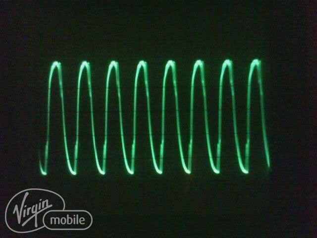
Upon wiring it up on the breadboard, this circuit produces a sort of ugly pseudo square wave, actually more like a capacitor charge/discharge waveform (or perhaps my oscilloscope isn't up to the task), but the signal is adequate to drive the counters. So that's the clock circuit.
About the counters. Starting with 4MHz, we need to divide by 2 and again by 2 to arrive at a 1MHz signal. Then divide that signal by 2 for 2X. Divide that same signal by 5 for 5X. The Heathkit circuit uses 1/2 of a 7474 dual flip flop to do the initial ÷ 2 (2MHz). The flip flop is wired to output a pulse for every other clock pulse it receives.
 A 7490 Decade Counter is used to output pulses for ÷ 2 (1MHz) and ÷ 5 (400kHz). A switch selects the 1X/2X/5X signal. Then the other 1/2 of the 7474 is used for a final ÷ 2 to get the 1MHz, 0.5MHz, or 0.2MHz signal selected by the switch. Five 7490's are used to divide this signal by 10, 100, 1K, 10K, and 100K.
Since I couldn't easily find any 7474's or 7490's, I looked around for various counters and ran across the 74393 Dual Binary Counter and hte 74162 Decade Counter. The '393 has four output pins, one per bit of the 4-bit (nybble) count, call them Q0-Q3. The Q0 signal is 1/2 the frequency of the clock input and the Q1 signal is 1/4 the clock frequency.
In case you're not up on binary counters used as frequency dividers... Counting in binary (000, 001, 010, 011, 100, 101, 110, 111) the Q0 bit goes high every other clock pulse, so if we feed our 4MHz signal into the '393's clock pin, Q0 oscillates at 2MHz. Likewise, the Q1 output it goes high every 3rd and 4th clock pulse, half as often as Q0, and 1/4 as often as the clock pulse, or 1MHz in our case. I didn't want to bother with a 5X option so for now my plans are for a switch to select 1X or 2X.
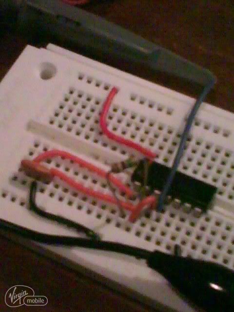
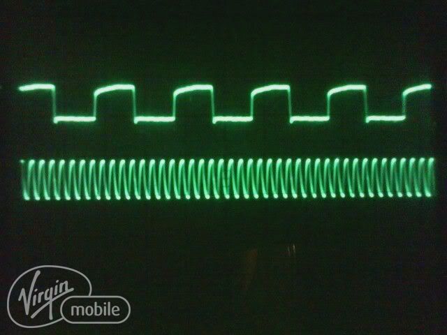
 On the breadboard, below left, I just hardwired the ÷ 4 (Q1) output. Initially I had problems getting the counter to work until I realized that the reset/clear/MR pin has to be wired low. Here's a scope trace showing the 1MHz pulsetrain on top and the original resonator/dual inverter output at the bottom.
The chip provides a terminal counter (TC) aka ripple counter (RC0) pin, and there are a few pins that have to be set high to get the desired behavior, as described in the datasheet. ENT is Enable Terminal Counter, ENP is Enable Parallel, and the datasheet says to tie CLR to high through a resistor. The 1MHz Q1 output from the '393 is fed into the clock input of the '162.
 Upon wiring this up on the breadboard (lower left), I was able to get pulses at a 100kHz frequency. The scope trace of the TC pin is shown at the top, the original 4MHz signal at the bottom. (By the way, I'm also finding my scope's timebase calibration is a little bit off).

 The TC outputs of each '162 will feed to a rotary switch that'll select the period/frequency of the signal and pass it along to the amplitude amplifier, which I'll experiment with next.
But for now, the proof of concept I wanted to put together for the clock and frequency divider is done. And it actually worked! How cool is that?
Part 2: Amplitude
Part 3: Power Supply
Part 4: coming soon
EDIT: two years later I've revisited this circuit again and am in the process of finishing the build.
A CERAMIC RESONATOR???? Those are accurate to about 5000ppm and exhibit quite a bit of temperature drift. You're looking at an error of about +/- 20kHz. Not a good choice for a calibration instrument! You really should consider a crystal for your oscillator. 30 - 30 ppm accuracy is doable quite cheaply.
ReplyDeleteThis is worth mentioning in the article so thanks for bringing it up.
ReplyDeleteAccording to the datasheet (http://www.lynxmotion.com/images/data/ztt.pdf) ±0.5% with ±0.3% temperature stability. So 12-32kHz error at 4MHz. I know.
But do you really think a 0.8% error on an analog oscilloscope trace is visible? Really? :)
Since I don't plan to use an analog 'scope to measure a frequency to anywhere near that level of precision, I'm not too worried.
That isn't to say that a crystal would be a bad idea and I'll no doubt upgrade. I think I recently salvaged a 4MHz crystal, in fact.
But anyway, the resonator is perfectly fine for this specific purpose.