No problem. Here's how.
Overview

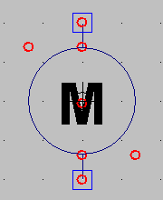
Whereas in MacSpice one has to manually set up files with subcircuits to be included for modeling complex devices, LTspice front ends these SPICE features by enabling the user to create new components. First, you draft a new symbol, in this case, I drew a typical motor symbol (right), a circle with an M in it, and two pins (ports) shown as squares.
Next you set up a schematic in the same directory and with the same base name as the symbol (e.g., motor.asy and motor.asc). You associate the pins/ports on the drawing with those in the schematic and now you can just plug in this component by adding it out of your directory just like you'd add any other LTspice component. This is a pretty clever approach that gives LTspice a lot of flexibility and power.
Behind the scenes, LTspice is using subckt cards to implement this hierarchy. It puts the subcircuit description inline in your circuit diagram when you load a component. You can see how this is implemented by selecting View > SPICE Netlist.
Walkthrough Example: Creating a Motor
Create a symbol. Select New Symbol from the File menu. Use the drawing tools in the Draw menu to create a circle with an M in the middle (schematic symbol for motor).
Circles are defined by clicking two points, upper left and lower right. You can use the drag tool to center it. Text is added with the text tool of course, and you would want to select centered justification.
Now it's time to add pins/ports. From the Edit menu, select Add Pin/Port (see image below left). Label the ports "a" and "b". Then click the location on the symbol where the port belongs. I added a port at the top and bottom. Now, draw a line/wire from each port to the main body of the device--the circle in this case (see image below right).
Save the file under LTspiceInstallDirectory\lib\sym\YourSubDirectory as an .asy file, such as motor.asy
Create a Subcircuit. A subcircuit is the schematic that is inside the symbol's "black box". Open a new schematic and draw the components that model your motor.
Let's just simply model the motor as a resistor. So, add a 16 ohm resistor, call it RM. Now, add two wires on each end of the resistor. You can always make the model more complex later.
Label each wire to match each port in your symbol. In our case, label the wires (aka nets) "a" and "b". Save the file into the same directory as the symbol file and give it the same motor base name. So save the file as motor.asc
Use the Component. Now, open a new schematic, and add a component. Select the motor component that should now appear (if for some reason it doesn't, make sure you opened a new schematic after creating the symbol; if all else fails restart LTspice). Add it to your schematic.
Toss in a voltage source, set it to 9 VDC. Wire it up and add a ground.
Click the Run Simulation tool. Click the DC op pnt (operating point) analysis tab. Click ok. The simulation should run and you should see some current through the motor component.
Here's a zip file of the files I created for this walkthrough: ComponentDemo.zip
And that's all there is to it.


Hi, I'm using LTspice and create my components in the same way that you do. However, sometimes it just doesn't work; I create the symbol and its schematic, am able to add the component to my circuit, but when I try to run the simulation, and error message pops up and says "Missing schematic of the hierarchy: (name of component)", and the netlist says the same. Any idea what could be causing this, and how to remedy it? Even after restarting LTspice multiple times, usually those that hadn't been working continue to malfunction in this manner.
ReplyDeleteThanks. Any help would be greatly appreciated.
Additional Information: When I open either schematic or symbol in LTspice and go to Hierarchy>>Open this Schematic's Symbol (or Open Schematic from the symbol), the correct corresponding symbol/schematic does pop up, so I don't see why it doesn't recognise the component on the larger circuit.
@Wayne: do you have any example files you can email me? Does this happen when you download schematics?
ReplyDeleteNext time it happens, try to view the spice error log and feel free to email it to me via the "contact me" link on this webpage. Will help if I can.
I think it's in the view menu but I don't have LTspice in front of me so am not sure.
I have the same problem :(
ReplyDeletehi, can you tell me how to use a *.cir file and attach it to a symbol? much appreciated
ReplyDeleteI found a fix for the "missing Schematic(s) of the hierarchy" error -- I had to move my .asy and .asc files into the same directory as my schematic.
ReplyDeleteThanks.
DeleteHi all,
ReplyDeleteThis is very useful to simplify circuits by introducing subcircuit blocks. But this method implies that you have to draw the schematic of each block.
But when you have to integrate into your circuit a custom and complex device whose definition/description is given by the producer in the form .SUBCKT, how you can associate this to a symbol?
Of course without redrawing the schematic...
This comment has been removed by the author.
ReplyDelete@django2oo5 http://video.linear.com/97 fast forward to about 9:20 in the video for adding a custom-drawn symbol for a SUBCKT. Also see @6:55 for another approach to doing this using an existing LTSpice symbol. Found it with a quick Google search "add subckt to ltspice"
ReplyDelete@shimniok thank you so much!
ReplyDeleteFor posterity, a possible solution to the "missing Schematic(s) of the hierarchy" error is to right click on the symbol in your schematic and setting the Prefix value to "X" (without quotations).
ReplyDelete